Muon system simulation
UglovTimofey (Talk | contribs) m (→Results) |
UglovTimofey (Talk | contribs) m (→Version 0.2) |
||
| (6 intermediate revisions by one user not shown) | |||
| Line 4: | Line 4: | ||
Optimal toolkit in this case is pure Geant4 simulation with simplified geometry and physics lists, able to produce fast results and estimate main parameters and characteristics of the detector. | Optimal toolkit in this case is pure Geant4 simulation with simplified geometry and physics lists, able to produce fast results and estimate main parameters and characteristics of the detector. | ||
| + | == Version 0.1 == | ||
=== Tasks for the 0.1 version of the simulation tools === | === Tasks for the 0.1 version of the simulation tools === | ||
| Line 37: | Line 38: | ||
To compare detector response in case of pions and muons, pion and muon of the same sign were generated in the same event with identical momenta. During the event reconstruction all hits were categorized according to the original particle. | To compare detector response in case of pions and muons, pion and muon of the same sign were generated in the same event with identical momenta. During the event reconstruction all hits were categorized according to the original particle. | ||
| − | == Results == | + | === Results === |
====Muon track smearing due to the multiple scattering==== | ====Muon track smearing due to the multiple scattering==== | ||
| Line 44: | Line 45: | ||
For the muon identification purposes high spacial resolution is not needed, the optimal value should be of order of the scattering spot. | For the muon identification purposes high spacial resolution is not needed, the optimal value should be of order of the scattering spot. | ||
| − | With the setup, described above, Monte Carlo simulation of the muon events for the | + | With the setup, described above, Monte Carlo simulation of the muon events for the 1st and 7th gap of absorber is shown. The smearing along Z axis is due to the multiple scattering on the calorimeter, magnet and absorber. Upper pictures corresponds to the energy-weighted position of the the hit, lower to the true position of muon/pion, respectively. The simulated physical process |
| − | [[File: | + | <math>e^+e^- \to J/\psi \to \mu^+ \mu^-</math> at E=3.096 GeV. |
| + | left: Magnetic field off ; right: magnetic field of 1.5 Tesla on | ||
| + | |||
| + | [[File:Mu 3.096 field off smearing.png]][[File:Mu 3.096 field on smearing.png]] | ||
| + | |||
| + | |||
| + | The same for process | ||
| + | |||
| + | <math>e^+e^- \to \tau^+ \tau^-</math> at E=3.3.55GeV. | ||
| + | left: Magnetic field off ; right: magnetic field of 1.5 Tesla on | ||
| + | |||
| + | [[File:Tau 3.55 field off smearing.png]][[File:Tau 3.55 field on smearing.png]] | ||
| + | |||
| + | ====Muon id feasibility study==== | ||
| + | |||
| + | With the setup, described above, Monte Carlo simulation of the muon events for the 1st and 7th gap of absorber is shown. The smearing along Z axis is due to the multiple scattering on the calorimeter, magnet and absorber. Upper pictures corresponds to the energy-weighted position of the the hit, lower to the true position of muon/pion, respectively. The simulated physical process | ||
| + | |||
| + | <math>e^+e^- \to J/\psi \to \mu^+ \mu^-</math> at E=3.096 GeV. | ||
| + | |||
| + | Magnetic field off: | ||
| + | |||
| + | [[File:Mu 3.096 field on layers.png]] | ||
| + | |||
| + | Magnetic field 1.5 Tesla on: | ||
| + | |||
| + | [[File:Mu 3.096 field off layers.png]] | ||
| + | |||
| + | |||
| + | The same for process <math>e^+e^- \to \tau^+ \tau^-</math> at E=3.3.55GeV. | ||
| + | |||
| + | |||
| + | Magnetic field off: | ||
| + | |||
| + | [[File:Tau 3.55 field on layers.png]] | ||
| + | |||
| + | Magnetic field 1.5 Tesla on: | ||
| + | |||
| + | [[File:Tau 3.55 field off layers.png]] | ||
| + | |||
| + | |||
| + | == Version 0.2 == | ||
| + | |||
| + | === Tasks for the 0.2 version of the simulation tools === | ||
| + | |||
| + | The main task for the second round of MC simulation is to supply the parametric simulation software with the data suitable for the fast simulation. | ||
| + | The initial particle momenta range is [0.5,1.5] GeV/c, particle type: pi+, pi-, mu+, and mu-. | ||
| + | |||
| + | |||
| + | === Geometry === | ||
| + | We used the same detector geometry as in the version 0.1, except for the fact, that endcaps of the same layer structure have been added. | ||
| + | The uniform magnetic field of 1.5T directed along beam line were applied to the volume inside the magnet coil. | ||
Latest revision as of 21:39, 21 May 2019
Contents |
[edit] This page is dedicated to the sketch standalone simulation of the SCT detector based on pure Geant4
One of the most important and urgent tasks for muon system technology choice and further optimization is to create a fast and reliable simulation tool. Optimal toolkit in this case is pure Geant4 simulation with simplified geometry and physics lists, able to produce fast results and estimate main parameters and characteristics of the detector.
[edit] Version 0.1
[edit] Tasks for the 0.1 version of the simulation tools
- Create geant4-based geometry description reflecting all main features influencing muon-related physics. The model are to be extendible to describe muon detector in detail if needed.
- Estimate basic features of the interacting muons (despite of the detector technology choice):
- Muon smearing due to the multiple scattering (depending of the muon energy, direction and/or specific production process; magnetic field ON/OFF)
- Desirable thickness of the muon system to reach maximal muon detection efficiency
- Muon/pion separation: decay point (detector layer) for the muons and pions of the same momentum, feasibility do distinguish processes based on this information
- Feasibility to distinguish pion kink: distinguish muons originated from the primary vertex and produced in the pion decays.
[edit] The geometry used in version 0.1 simulation
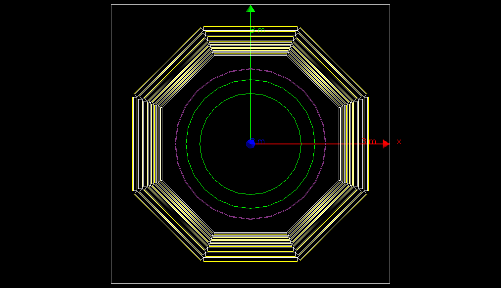
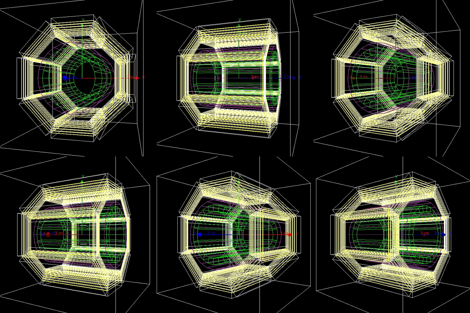
The following geometry is based mostly on the this drawings.
For simplicity, only the barrel part of the detector was simulated. The full simulation is possible, but not urgent for the first estimation.
- The following parts of the detector were simulated:
- CsI calorimeter (inner radius 1090mm, thickness 297.6 mm, which corresponds to 16 X0)
- Magnet coil (inner radius 1610mm, thickness 14.4 mm of copper, which corresponds to 1 X0)
- 9 iron absorber layers in octant geometry (see the drawings). The distance to the innermost layer is 1900mm from the beamline, the thickness of the absorber layers 30 mm,30 mm,30 mm,40 mm,40 mm,80 mm,80 mm,80 mm, respectively, which roughly corresponds to 1.7 X0, 1.7 X0, 1.7 X0, 2.3 X0, 2.3 X0, 4.5 X0, 4.5 X0, 4.5 X0.
- The 30 mm gaps between the absorber layers could be filled with organic scintillator for the energy measurement (not needed for now)
- Internal elements of the detector are estimated to give from 0.35 X0 to 0.6 X0 and are neglected in this study
- Magnetic field is NOT simulated (could be turned on if needed, though)
- Green: CsI calorimeter
- Violet: Cu magnet coil
- White: Fe absorber layers
- Yellow: Organic scintillator gaps
[edit] The source
Muons and pions were simulated as particles originated from the primary vertex according to the various physical distribution, taken from these samples. To compare detector response in case of pions and muons, pion and muon of the same sign were generated in the same event with identical momenta. During the event reconstruction all hits were categorized according to the original particle.
[edit] Results
[edit] Muon track smearing due to the multiple scattering
One of the base characteristics of the muon system is spacial resolution. Since all charged tracks are subjected to the multiple scattering on the material of the inner detectors and absorber, and soft tracks scatters stronger, the use of the muon system as tracking detector is questionable. For the muon identification purposes high spacial resolution is not needed, the optimal value should be of order of the scattering spot.
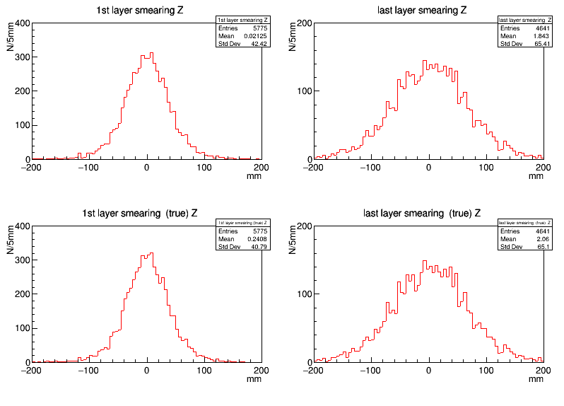
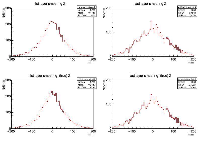
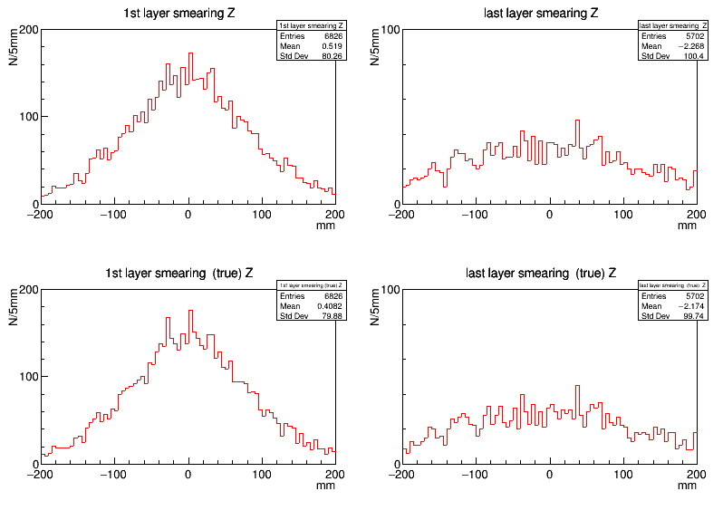
With the setup, described above, Monte Carlo simulation of the muon events for the 1st and 7th gap of absorber is shown. The smearing along Z axis is due to the multiple scattering on the calorimeter, magnet and absorber. Upper pictures corresponds to the energy-weighted position of the the hit, lower to the true position of muon/pion, respectively. The simulated physical process
at E=3.096 GeV.
left: Magnetic field off ; right: magnetic field of 1.5 Tesla on
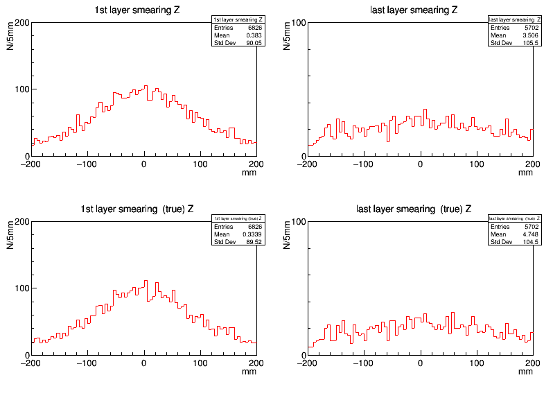
The same for process
 at E=3.3.55GeV.
left: Magnetic field off ; right: magnetic field of 1.5 Tesla on
[edit] Muon id feasibility study
With the setup, described above, Monte Carlo simulation of the muon events for the 1st and 7th gap of absorber is shown. The smearing along Z axis is due to the multiple scattering on the calorimeter, magnet and absorber. Upper pictures corresponds to the energy-weighted position of the the hit, lower to the true position of muon/pion, respectively. The simulated physical process
 at E=3.096 GeV.
Magnetic field off:
Magnetic field 1.5 Tesla on:
The same for process  at E=3.3.55GeV.
Magnetic field off:
Magnetic field 1.5 Tesla on:
[edit] Version 0.2
[edit] Tasks for the 0.2 version of the simulation tools
The main task for the second round of MC simulation is to supply the parametric simulation software with the data suitable for the fast simulation. The initial particle momenta range is [0.5,1.5] GeV/c, particle type: pi+, pi-, mu+, and mu-.
[edit] Geometry
We used the same detector geometry as in the version 0.1, except for the fact, that endcaps of the same layer structure have been added. The uniform magnetic field of 1.5T directed along beam line were applied to the volume inside the magnet coil.
